Exploring Tube Finning for Increased Heat Exchanger Performance
Introduction to Tube Finning and Inserting
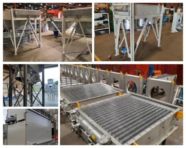
Tubes are used very widely in heat exchangers. When you pass a liquid or gas along a tube you can transfer its heat to a separate liquid or gas on the outside of the tube.
A heat exchanger can comprise of 1 single tube, or they can have 10’s or even 100’s of tubes in bundle.
The Problem with Plain Tube
On its own a plain tube does not perform very well in a heat exchanger. The liquid can easily pass through the tube and retain a lot of its heat without ‘exchanging’ it to the liquid on the outside of the tube. So to greatly improve the thermal performance of the heat exchanger the designer will explore all options to extend the surface area of the outside of the tube.Our Solution: Tube Finning
To significantly improve the thermal performance of the heat exchanger, the designer will explore all options to extend the surface area of the outside of the tube.The most common and reliable method of extended surface is tube finning. Attaching a fin to the outside of the tube greatly improves the performance of the heat exchanger especially if the application is air cooling a liquid.
Turbulators
In addition to external finning, it is also possible to apply turbulators inside the tube. Turbulators can be pulled into a tube. These help mix the flow as it passes the inside of the tube and help conduct the heat too.Cost Efficiency
When you apply the optimum external tube finning and internal turbulator the heat exchanger designer can maximise the heat exchanger layout and result in the most compact and cost-effective solution. Typically, the tube is more expensive than the fin and turbulator material so a smaller unit (with less tube length) is more cost effective. Also, a smaller weight and size unit is often desirable for applications such as automotive, offshore oil and gas or on top of industrial buildings.Types of Heat Exchangers that use Finned Tube
- Dry Coolers
- Finned Tube Air Exchangers
- Seal Cooler
- Air Blast Coolers
- Air Cooler
- Air Cooled Heat Exchangers
- Fin Fan Coolers
- Heat Exchanger
- Air Exchangers
Industries and Applications for Finned Tube
- Industries
- Oil and Gas
- Petrochemical
- Food and Beveridge
- Nuclear
- Marine
- Renewable
- Power Generation
- Pulp and Paper
- Hydrogen
- Carbon Capture and Storage
- Data centres
- Electrical
- Sugar
- Wind Power
- Tidal Power
- Tobacco
- Automotive
- Steel
- Process Liquids and Applications
- Condensers
- Gas
- Liquid
- Hydrocarbons
- Lubricating Oil
- Hydraulic Oil
- GazPaks
- Purge Air
- Water
- Steam
- Inter cooler
- After cooler
- Seal Air
- Seal Fluids
- Vacuum Steam Condensers
- Flue Gas
- Economisers
- Hydrogen
- Machines and Plant
- Gas Turbines
- Pumps
- Compressors
- Engines
- Cars
- Trucks
- Transformers
- Exhausts
- Flue Stacks
- Data Centres
- Mills
- Refinery
- Seal Systems
- Factories
- Buildings
- Hospitals
- Shopping Centres
- Ships
External Fin Tubing
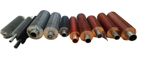
Common External Fin Types
1. L Fin Tube
The L Fin uses a flat strip of material. The finning machine bends a 90-degree L shaped foot on the strip and then wraps the strip around the tube. The fin stands up on the L foot and is held in place by the curl of the fin to match the tube outside diameter, the foot and the tension of the wrap. To hold the end of the strip in place the strip is folded or stapled back to the adjacent fin.
2. LL Fin Tube
The LL Fin is very similar to L fin except the foot is longer. The longer foot overlaps with the foot of the adjacent fin so that all the feet are overlapping.
3. G Fin Tube
The ‘G’ of G Fin stands for groove. The edge of the fin strip is embedded in the tube wall. First the finning machine peens back a groove in the tube wall then it applies a curl to the fin strip and embeds it into the groove. The groove then closes up and securely attaches the fin strip. Because the strip is positively engaged into the tube material G fin can withstand higher temperatures that L fin.
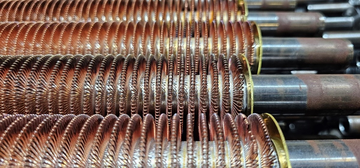
4. Wire Wound Fin Tube
The Wire fin has loops of wire bound to the tube. First, they are bound in place with a binding wire then those loops are soldered into position. WW Fin gives outstanding increase to surface area and thermal performance.
5. Crinkle Fin Tube
Instead of applying a curl to the fin strip crinkle fin is simply wrapped around the tube edge on. The foot of the fin strip crinkles to form a stable ‘wavey’ foot and the top of the fin remains straight. The tube is knurled to provide the crinkle foot additional purchase. The start and finish of the fin is spot welded to secure the strip.
6. KL Fin Tube
The ‘K’ stands for knurled. KL fin is the same as L fin except the tube is knurled to provide additional purchase to the tube.
7. Extruded Fin Tube
An Extruded Fin has a larger tube of the desired fin material is slid over the tube as a sleeve. Then a series of plate rollers press into the sleeve tube causing the formation of fins. The resulting fin is one solid body completely covering the tube.
8. Low Fin Tube
A Low fin is produced using a similar method as extruded fin, but instead of using a sleeve material it presses the base tube metal in the plate rollers to create a fin. Because it is the tube material that is used it is not possible to create a very tall fin without compromising the integrity of the base tube.
Fin Selection table
| Fin Type | Max Temp (°C) | Max Fin Height | Heat Transfer | Aluminium | Copper | Steel | Stainless Steel |
|---|---|---|---|---|---|---|---|
| L Fin | 150 | high | good | YES | YES | NO | NO |
| LL Fin | 175 | high | good | YES | YES | NO | NO |
| G Fin | 450 | high | good | YES | YES | YES | YES |
| Wire Wound Fin | 250 | medium | great | YES | YES | NO | YES |
| Crinkle Fin | 150 | medium | good | YES | YES | NO | NO |
| KL Fin | 200 | high | good | YES | YES | NO | NO |
| Extruded Fin | 250 | medium | good | YES | YES | NO | NO |
| Low Fin | same as tube | low | low | YES | YES | YES | YES |
Obtaining the Best Fin Selection for Individual Heat Exchangers
As a manufacturer and supplier of heat exchangers, we utilise thermal design calculations to reach the best fin selection for each heat exchanger. There are many variables that need to be considered before the most
suitable and efficient design is reached. The temperature limitation of each type of fin is one of the main drivers for which type of fin to use.
The temperature limits of the table above are guaranteed by the TFL division of Specialist Heat Exchanger Limited based in the UK (other manufacturers may vary). Then the fin height and thermal conductivity of the fin material selected is the next priority. The main purpose of the fin is to extend the surface area of the outside wall of the tube to give better heat transfer. There are also mechanical considerations such as corrosion resistance, fin strength and ease of cleaning.
The most competent suppliers will use commercially available design software such as HTRI or ASPENTech and this may be enhanced with inhouse design tools too. This software will help establish the fin selection.
Internal Tube Inserts / Turbulators
It is possible that the external tube heat transfer finning will not be the most controlling factor for viscous fluids such as oil. Where viscous liquids are being cooled the addition of a tube insert or turbulator may have
great impact. The turbulator helps heat transfer of fluids by disturbing the laminar flow creating turbulence in the fluid flow. The designer will maximize the internal and external tube surfaces to ensure the most economical
design also with full consideration to the fluid properties and allowable pressure drop.
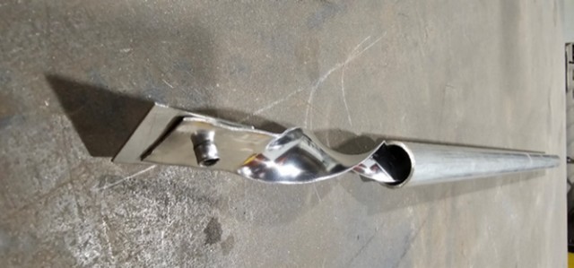
Bonded Tube Inserts
Some suppliers can also offer very high-performance bonded tube inserts. These are soldered inside the tube to provide both: turbulence and heat conduction. Bonded inserts are not currently covered by commercial design software
such as HTRI or ASPENTech but can greatly increase the thermal heat transfer. For example, a bonded insert can enable 6 times more heat transfer than a twisted strip insert and 3 times more heat transfer that a ‘non bonded’
pull in wire insert.
Tube Finning Manufacturing
Tube finning is a specialist operation and requires tube finning machines to apply the fin to the tube.
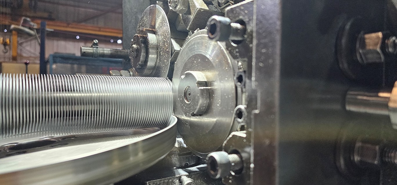 For ribbon fin such as G, L and LL the tube is gripped and rotates in the finning machine while the fin is formed and applied to the tube under tension. Flat ribbon/strip is fed into a pan and pin which compress the strip forming
a curl to match the tube diameter. Good quality fin will stand up 90° from the tube and will be well attached making good contact with the tube.
For ribbon fin such as G, L and LL the tube is gripped and rotates in the finning machine while the fin is formed and applied to the tube under tension. Flat ribbon/strip is fed into a pan and pin which compress the strip forming
a curl to match the tube diameter. Good quality fin will stand up 90° from the tube and will be well attached making good contact with the tube.
Ribbon Fin
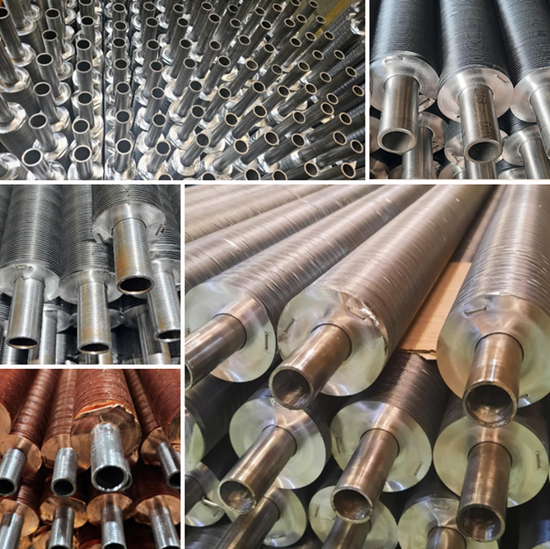
Wire Wound Fin
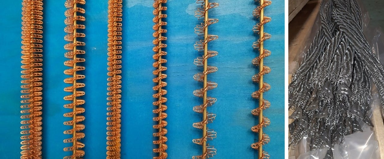
Tube inserts may be ‘pull in’ type made from wire mesh or twisted strip; OR they could be higher performance bonded turbulator where the insert is soldered to the inside of the tube. Bonded inserts are only manufactured by the most
experienced tube suppliers.
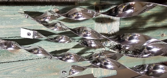
Twisted Strip
Wire Pull-in
Summary: The Advantages of Using Fin Tube in Heat Exchangers
Finning and inserting tube is an excellent way to boost heat transfer of a heat exchangers. Thermal engineers can optimise the tube external and internal heat transfer by applying different extended surfaces and turbulators. For viscous
fluids such as oil, the bonded tube insert is superior and can reduce the exchanger cost, size and weight. Different fins and attachment methods have different operating temperature limits. Finned tubes that are correctly selected should
last many years with minimal maintenance.
Vendor Selection - Tube Fins Finning Machines
Tubefins is the finning division of Specialist Heat Exchangers Limited based in the UK and is an excellent choice of supplier for the following reasons:
• Tubefins operates the highest quality HERCOL tube finning machines. The HERCOL positively grips the tube with collets and chucks (rather than the less precise methods).
• Tubefins can offer bonded tube inserts which can perform 6 times better than pull in inserts for viscous process fluids, such as oil.
• Tubefins can apply carbon steel and stainless steel fin where other finning companies cannot.
• Tubefins has refined their manufacturing of finned tubes, building every day on experience since year 1968 with tens of thousands of operational tubes commissioned successfully around the world.
• Specialist Heat Exchangers fin their own tube to a high standard using propriety HERCOL tube finning machines with positive collet and chuck drive mechanism which give superior fin attachment for all L, LL and G fin tube.
• Tubefins manufacture in the UK in Lincoln city.
• Tubefins hold ISO 9001, 14001 and working towards 45001 and 27001.
• Tubefins hold ESG policy aligned with government initiatives to achieve net zero 0 by 2050.
• Tubefins have an online tube fin configurator: Configure your own tube specifications ready for quotation.
Further information and contact details can be found on the TubeFins and Specialist Heat Exchangers websites:
https://tubefins.co.uk
https://specialistheatexchangers.com
Typical Applications for Finned Tubes